
QRG - Power Generators

Electricity is produced by various types of generators, which are typically referred to by their fuel type, such as coal, nuclear, gas, hydro, wind, or solar. While these terms are familiar to most people, few outside the utility industry understand how these generators actually produce electricity. The intent of this brief article is to provide a basic overview of the various types of generators to serve as a quick reference guide (QRG) for those not familiar with how electricity is generated.
Generator Terminology
First, let’s define a few important terms that are associated with power generation.
Capacity – the maximum output that a generator can produce. Typically expressed in kilowatts (kW) or megawatts (MW). This is the rating of a generator and system operators depend on capacity being available for dispatch to ensure reliability and supply adequacy.
Energy – the amount of power that a generator delivers over a period of time, usually measured in kilowatt-hours (kWh) or megawatt-hours (MWh).
For example, a 100 MW generator that operates at full capacity for 2 hours produces 200 MWh of energy (100 MW X 2 hrs = 200 MWh)
Capacity Factor – the ratio of energy that a generator actually produces over a given time period to the theoretical maximum amount of energy the generator can produce over the same time period. Capacity factors are typically measured over one year.
Base Load – generators with capacity factors of 80% to 95%
Intermediate Load – generators with typical capacity factors of 35% to 65%
Peak Load – generators that operate during peak demand periods, with typical capacity factors of 5% to 25%
Thermal Generator - a generator that converts thermal energy (heat) into electrical energy, typically through a combustion process
Thermal Efficiency – the efficiency with which thermal energy (heat) is converted to electrical energy, measured in %
Heat Rate – the ratio of fuel energy input to electrical energy output, usually measured in British Thermal Units per kilowatt hour, Btu/kWh
Heat Rate (Btu/kWh) = Energy Input (Btu) / Electrical Energy Output (kWh)
Relationship of Thermal Efficiency to Heat Rate
Thermal Efficiency (%) = 3413 / Heat Rate (Btu/kWh)
1 kWh = 3413 Btu
Example: What is the thermal efficiency of a generator with a heat rate of 10,500 Btu/kWh? Thermal Efficiency = 3,413 / 10,500 = 32.5%
Basic Thermal Generator Principles
While there are various types of thermal generators, the basic principles underlying all thermal generators are the same:
Thermal energy (heat) is produced by the combustion of a fuel (liquid, solid, or gas) or through a nuclear reaction
The thermal energy is then transferred to a working fluid
The working fluid is used to drive a turbine which converts the thermal energy into mechanical (kinetic) energy
The turbine spins a generator which converts the mechanical energy into electrical energy
All thermal generators are “synchronous” with the transmission system, which means they are directly electrically coupled to the grid through their alternating current (AC) generators
Because thermal generators are synchronous, the rotating masses of their turbines and generators provide angular momentum, also know as inertia, to the power system to help maintain frequency stability
AC Generator Principles
Here are some basic operational principles of alternating current (AC) generators:
An AC generator converts the mechanical (kinetic) energy of a turbine into electrical energy
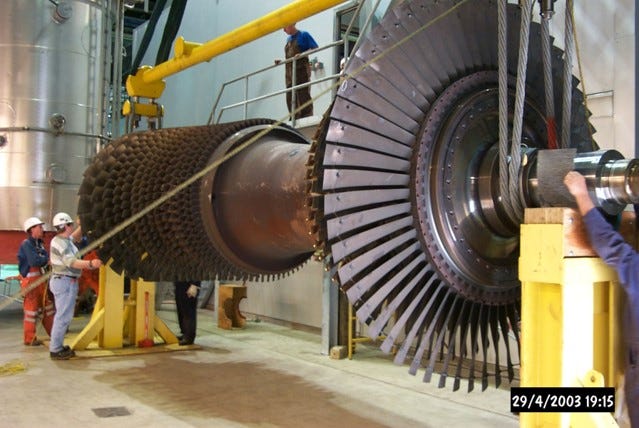
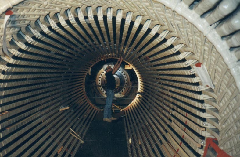
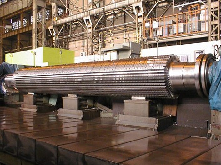
An AC generator consists of two main components – a rotor and a stator. The photos above illustrate what these look like
The rotor is basically a large magnet that creates a rotating magnetic field using regulated DC voltage via “slip rings” that connect the rotating shaft to the voltage source
The stator is made of wire conductor loops wound around an iron core – the power generated by the turbine flows through the generator’s stator to the transmission system
The rotor rotates within the stator and induces an electrical current in the stator winding through electromagnetic induction, which is when voltage is created across the terminals of a looped conductor when it passes through a magnetic field
The generator rotor consists pairs of magnetic north and south “poles”
The frequency of the voltage produced by a generator depends on rotational speed and the number of pairs of generator poles
Frequency (Hz) = (Rotational Speed (RPM) X # of pole pairs) / 60
In a 60 Hz system, the maximum rotational speed a generator can obtain is when it has one pole pair
Rotational Speed (RPM) = {frequency X 60} / # of pole pairs
RPM = 60 X 60 / 1 = 3600 RPM
For a 50 Hz system, the maximum rotational speed a generator can obtain is:
RPM = 50 X 60 / 1 = 3000 RPM
High speed generators, such as gas and steam turbines, have 1 pole pair and therefore spin at system frequency (60 or 50 Hz)
Very large diameter generators, such as hydro turbines, must spin at much lower speeds, such as 120 or 150 RPM, due to their large mass and therefore have many more pole pairs
For example, a 60 Hz hydroelectric generator that spins at 150 RPM has 24 pole pairs
# of Pole Pairs = 60 X 60 / 150 = 24 pole pairs
Steam Turbines
A thermal generator that uses steam to rotate the turbine and generator is known as a steam turbine, and has the following characteristics:
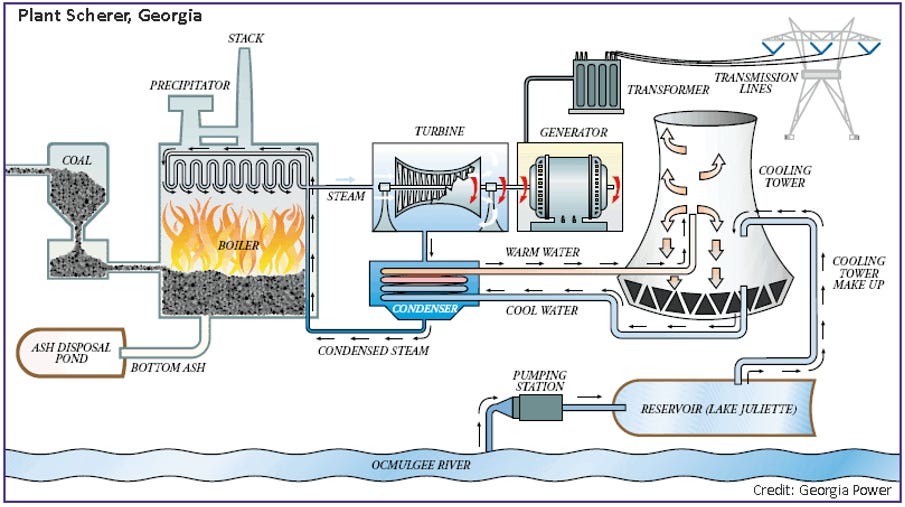
Coal-fired plants and nuclear plants both produce electricity using steam turbines
In both cases, the working fluid is steam
Coal, natural gas, oil, or biomass is burned in a large boiler which heats water to produce high pressure/temperature steam, or a nuclear reaction is used to produce high pressure/temperature steam in a large boiler that is sent to the steam turbine through high pressure pipes
After the steam enters the turbine, it expands through a series of blades that increase in length as the steam travels along the turbine to maximize the energy transfer from the steam as it expands and loses energy
The steam exits the turbine and is condensed back to water in a condenser
The water is then heated back into steam and the cycle repeats
The steam turbine is directly coupled to an AC generator to create electricity
Steam turbines are large and have a lot of mass, which means they must be slowly and evenly heated up to operating temperature to avoid differential heat zones in the turbine that can warp and damage it. In addition, the boilers and steam piping must also be evenly heated up for the same reasons. Therefore, steam turbines have long startup times that can range from 8 to 10 hours when started from ambient temperature.
Steam turbines are used primarily in base load applications
Typical Thermal Efficiencies range from 28% to 36%
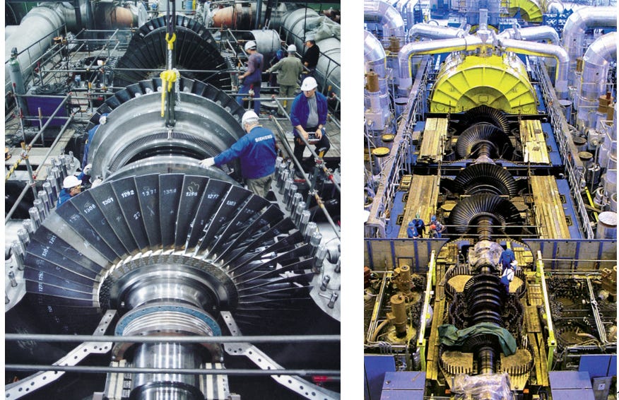
Simple Cycle Gas Turbines
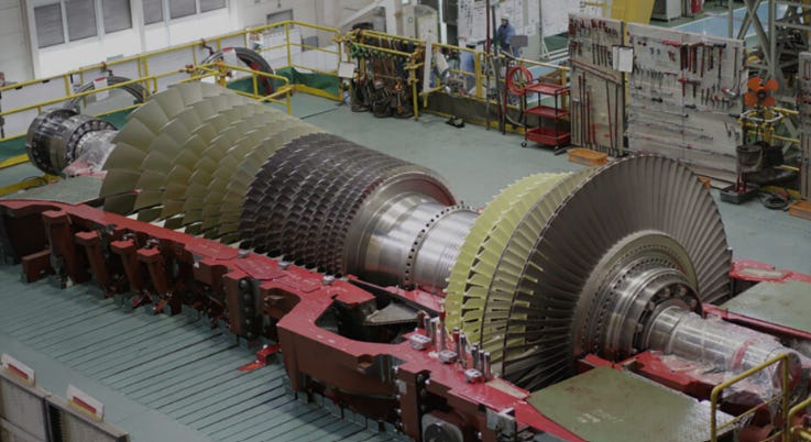
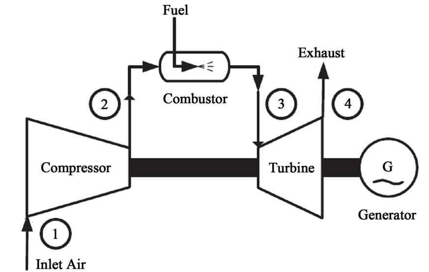
A simple cycle gas turbine (SCGT), is also known as an open cycle gas turbine, gas turbine, or “jet engine”. The gas turbines used to power aircraft are similar to, and in some cases almost identical to, the gas turbines used to generate electricity. A simple cycle gas turbine has three basic components - a compressor, a combustion chamber, and a power turbine. The gas turbine is connected to a generator to create power. Here are the basic operational principles:
Atmospheric air is sucked in and compressed by the compressor
The working fluid is air
Liquid (diesel, aviation fuel) or gaseous fuel (natural gas) is added to the compressed air and the mixture is ignited in the combustion chamber
The high pressure/temperature combustion gas is expanded through the blades of the power turbine and then exhausted to atmosphere
The sequence can easily be remembered as: Suck - Squeeze - Bang - Blow!
The turbine is coupled to an AC generator to produce electricity
Simple cycle gas turbines use high temperature tolerant nickel based superalloys which allows them to be warmed up quickly, so they have fast startup times that range from 10 to 45 minutes when started from ambient temperature
They are typically used for peaking and to provide operating reserves on short notice
Typical Thermal Efficiencies range from 29% to 40%
Combined Cycle Gas Turbines
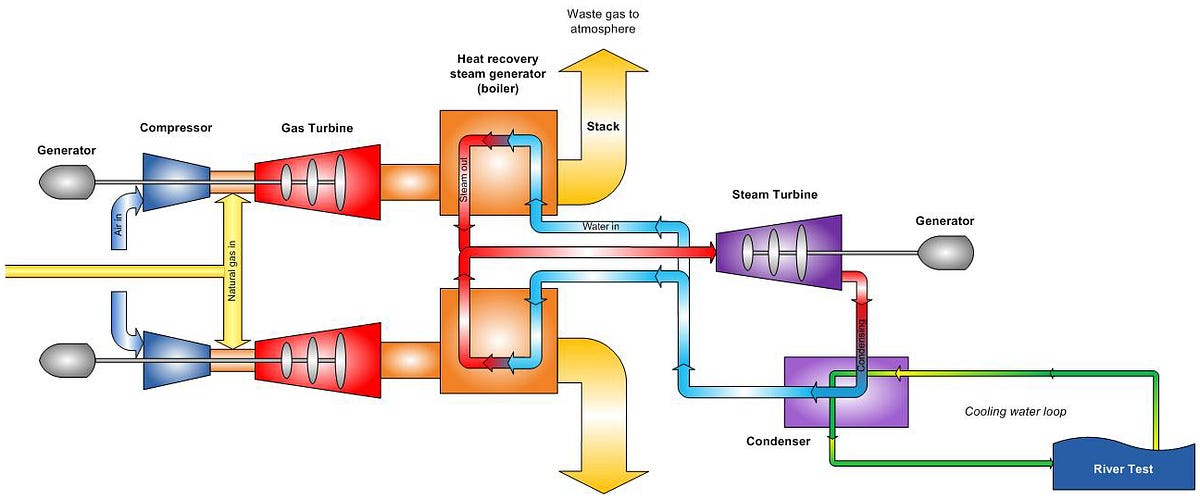
A combined cycle gas turbine (CCGT) is simply the combination of one or more gas turbines with a steam turbine. Here are the basic operational principles:
Since a CCGT combines gas and steam turbines, the working fluids are both air and steam
The gas turbine operates exactly as described in the Simple Cycle Gas Turbines section above. However, once the hot gases pass through the turbine, instead of being exhausted to atmosphere, they are directed through a boiler to create steam
The steam is then expanded through the blades of a steam turbine as described in the Steam Turbines section above
AC generators are connected to both the gas and steam turbines to produce electricity
Due to the combination of gas and steam turbines, the startup times for CCGTs are between 3 to 8 hours
CCGTs are more operationally flexible than pure steam turbines and are used for both intermediate base load applications
CCGTs have the highest Thermal Efficiencies of all thermal generators, typically in the 45% to 62% range
Hydroelectric Generation
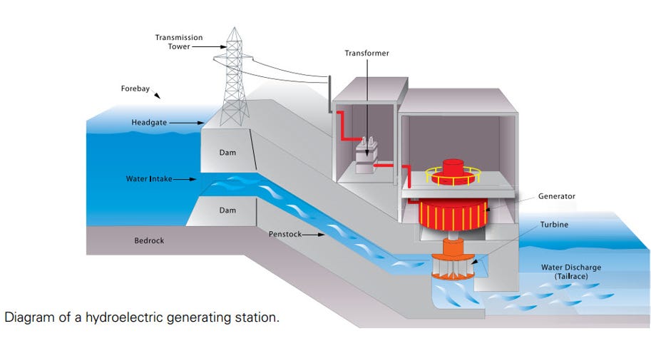
One of the oldest ways to generator electricity is through the use of water. A hydroelectric generator is simply a large turbine that is rotated by water and connected to an AC generator to produce electricity. Here are the basic operational principles:
Water, either from a river or a man-made reservoir, is directed through a channel or penstock
The water then moves through gates to control the flow rate, called wicket gates
After passing through the wicket gates, the water then rotates a turbine
The working fluid is water
The turbine drives an AC generator to produce electricity
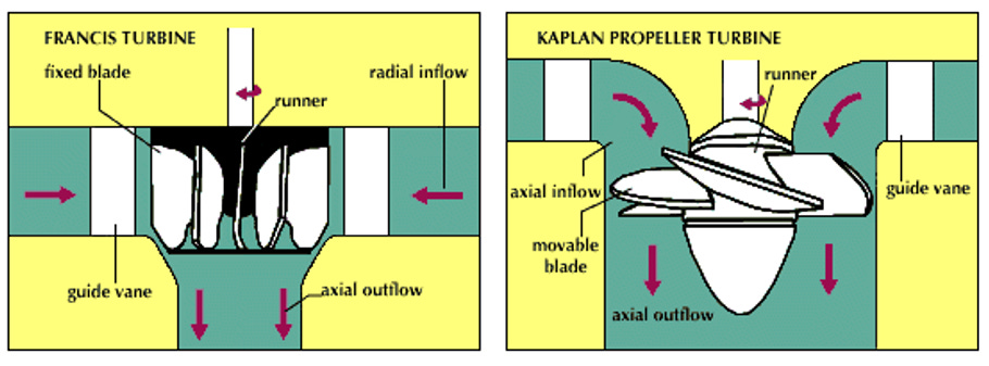
There are three types of hydroelectric turbines:
Francis turbine: combines axial and radial flow, has fixed blades, and is vertically oriented – this is the most common type of hydroelectric turbine
Kaplan turbine: an evolution of the Francis turbine with adjustable blades
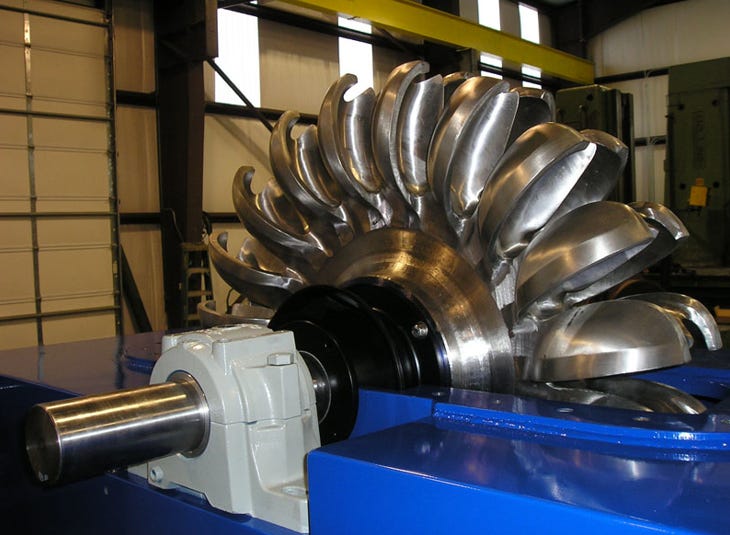
Pelton wheel: tangential flow device that is essentially a “bucket” wheel that is driven by the “impulse” of water on the buckets, horizontally oriented
Wind Turbines
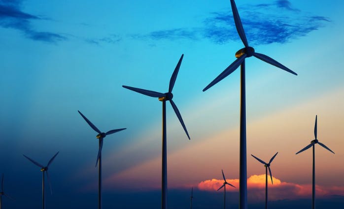
Wind turbines are relatively simple. Wind travels through the blades of a large turbine that is connected to a generator to produce electricity. However, unlike thermal generators, wind turbine generators are not synchronous because the speed of the generator varies with wind speed, so the generator uses sophisticated power electronics (inverters) to transmit electricity to the grid at the correct frequency and voltage. For this reason, wind turbines are known as inverter-based resources (IBR).
The working fluid is air and typical wind turbine sizes range from less than 1 MW to 5 MW, but sizes are increasing and there are some wind turbines that exceed 10 MW.
Solar Power
There are two types of utility scale solar power systems:
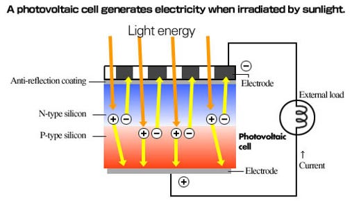
Solar Photovoltaic (PV) which converts solar light directly into electricity using semiconductors. Electricity is generated by the “photovoltaic effect” in which a semiconducting material absorbs photons of light and emits electrons to produce an electric current
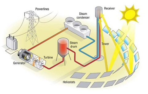
Concentrated Solar Power (CSP), which uses mirrors or lenses to concentrate sunlight into powerful beams that are used to heat water or a salt solution to create steam to drive a steam turbine
Similar to wind generators, PV systems use sophisticated power electronics (inverters) to transmit electricity to the grid, and are known as inverter-based resources (IBR).
Both PV and CSP plants require large areas of land
Conclusion
While there are many different types of generators, there a some common basic principles of operation:
Almost all power generators convert mechanical energy to electrical energy through the use of a working fluid – gas, steam, air, or water
Coal-fired power plants and nuclear power plants use steam turbines
Combined cycle power plants use both gas and steam turbines
Only solar PV produces electricity directly with no working fluid
Gas turbines, steam turbines, and hydroelectric turbines are synchronous generators because they are directly electrically coupled to the grid
Wind and solar generators are connected to the grid via power electronics and are known as inverter-based resources (IBR)
Good roundup. When discussing each type you could list the capacity factor for each from AESO or other canadian regulators?
Spen the day terminating a new comm cable on my little home standby. Principals are all the same.